Project Examples
System Engineering & Modeling
System Engineering/Modeling
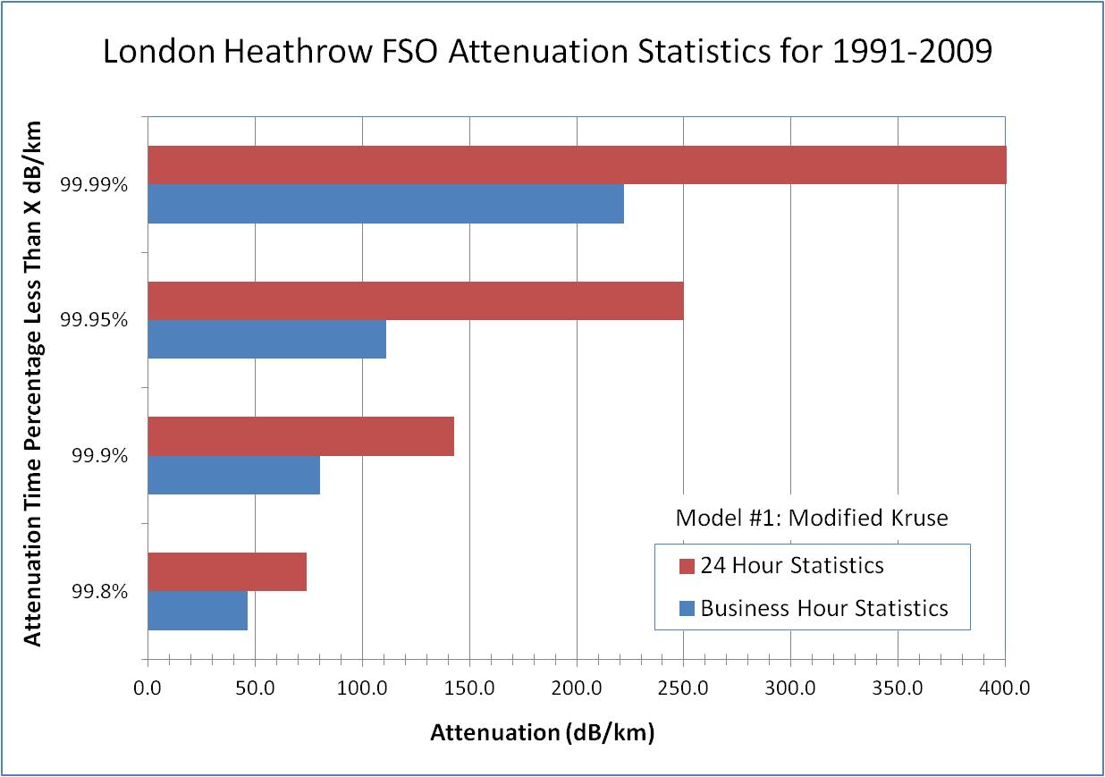
Visibility statistics for London converted to attenuation statistics in dB/km loss. Crunched data was 5 minute visibility from Heathrow Airport. This data can be used for Free Space Optics (FSO) link budgets to determine things like link availability versus link distance given the FSO terminal specifications.
MMW-FSO Hybrid Link–Distance vs. Availability
Photonics & Fiber-Optics, Point-to-Point Links, System Engineering/Modeling
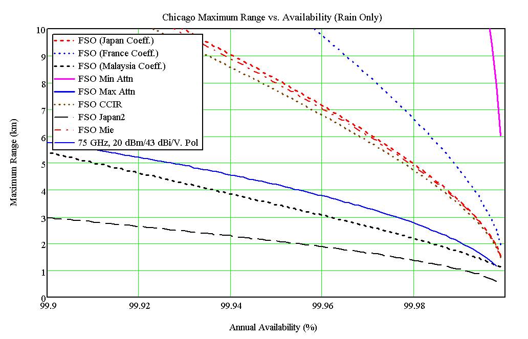
Maximum distance vs. availability for a hybrid MMW/FSO link in Chicago using certain FSO and MMW radio specifications.

FSO Up-Time Percentage in a Hybrid MMW/FSO link
Photonics & Fiber-Optics, Point-to-Point Links, System Engineering/Modeling
Plot assumes that the MMW radio link is the primary link. Calculation assumed certain FSO and MMW radio specifications.
Broadband Wireless–Financial Analysis
Outdoor RF Coverage, System Engineering/Modeling
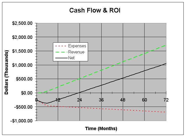
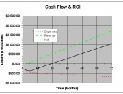
Financial analysis for a particular outdoor broadband wireless deployment assuming certain monthly subscription fees, market penetration, base station density, capital, and recurring network expenses (ROI = Return on Investment).
RF Loss Through Trees
Outdoor RF Coverage, System Engineering/Modeling
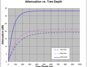
Example RF Loss versus tree depth at various frequencies. Exact loss coefficients will depend on the tree type and density (evergreen, deciduous, wet evergreen forest, etc.).
Ground to Space Optical Attenuation
Photonics & Fiber-Optics, System Engineering/Modeling
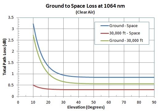
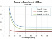
Modeling of ground to space attenuation at 1064 nm for NASA's "Ride-the Light" project.
HF Communications Modeling
Point-to-Point Links, System Engineering/Modeling
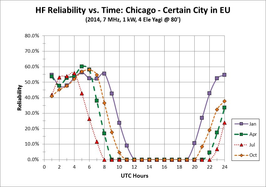
Example modeling of ionospheric HF propagation reliability as a function of frequency, time of day, season, and year. Not shown: corresponding point-to-point latency modeling outputs and measurements.
Modeling of Ice Attenuation on Antenna Radome
Point-to-Point Links, System Engineering/Modeling
Attenuation verses antenna radome ice thickness was calculated based on the measured complex permittivity of ice at various microwave frequencies.
Optical Fiber Link Budgets
Photonics & Fiber-Optics, System Engineering/Modeling
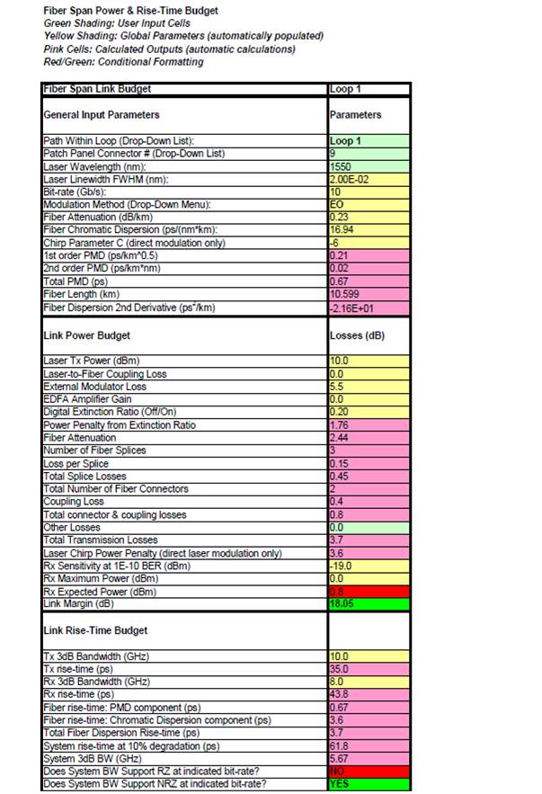
Optical fiber link budget that automatically reads measured attenuation, chromatic and polarization-mode dispersion as a function of wavelength. Spreadsheet also allows inclusion of measured splice or connector losses, and laser/modulation types to be included for the power and rise-time link budgets.

Optical Fiber Chromatic Dispersion Measurements
Photonics & Fiber-Optics, System Engineering/Modeling
Measured chromatic dispersion as a function of DWDM wavelengths and curve fit of dispersion versus wavelength to be used in the fiber link budget.
Optical Fiber Attenuation vs. DWDM Wavelength
Photonics & Fiber-Optics, System Engineering/Modeling
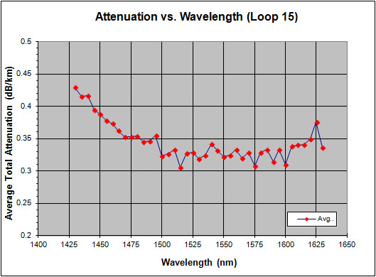
Optical fiber attenuation versus wavelength and curve fit for inclusion into the fiber link budget.
Optical Fiber PMD Measurements
Photonics & Fiber-Optics, System Engineering/Modeling
Optical fiber Polarization Mode Dispersion (PMD) measurements. Older installed optical fibers may not have a PMD specification, in which case it is necessary to measure the PMD to ensure the fiber segment can support higher modulation rates. In this project, fiber PMD was measured as preparation for a network upgrade to OC-192, where we tagged individual fibers that would not be able to support OC-192 (10 Gbps) due to an excessive PMD.
Measured PMD Statistics
Photonics & Fiber-Optics, System Engineering/Modeling
PMD statistics for a service provider's fiber-optic network. Note that some optical fibers in this network were over 15 years old, which accounts for the larger PMD values.
Maximum Fiber Distance vs. PMD
Photonics & Fiber-Optics, System Engineering/Modeling
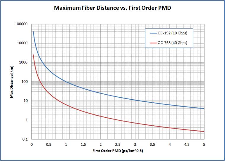
Calculated maximum fiber distance vs. Polarization Mode Dispersion (PMD) and data-rate (assumes no external PMD compensation).
Lab Simulation of Microwave Fading
Point-to-Point Links, System Engineering/Modeling
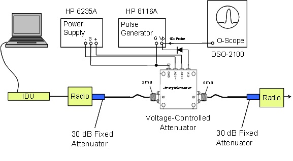
A lab simulation was implemented using a voltage controlled variable attenuator driven by a function generator to create arbitrary fade events to assess switching performance in a protected SONET ring.
HF Antenna Design & Modeling
System Engineering/Modeling
7 MHz antenna designed for a limited space environment using finite element modeling.
3D HF Antenna Pattern
System Engineering/Modeling
Antenna pattern assuming actual ground conductivity at 7 MHz for previously shown antenna design.
2D HF Antenna Elevation Pattern
System Engineering/Modeling
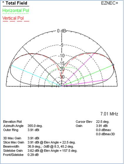
Plot shows the bi-directional gain and radiation angle for a 7 MHz HF antenna design.
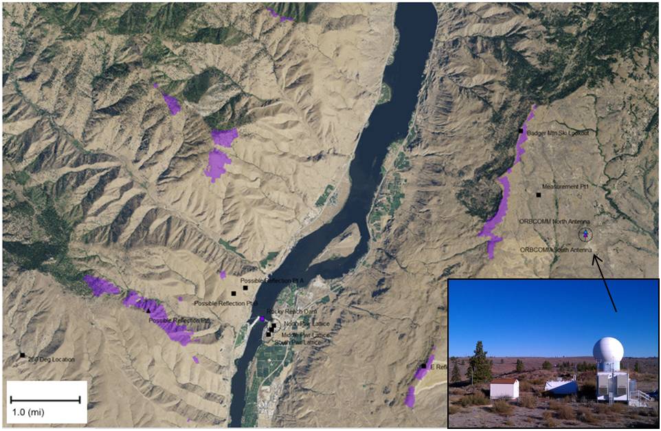
Satellite Ground Station Noise Measurements
Outdoor RF Coverage, Point-to-Point Links, System Engineering/Modeling
Violet areas are near-line-of-sight regions common to the suspected noise source and the Satellite ground station, which experienced more noise when pointed in the Azimuth direction of a hydroelectric dam.

