Project Examples
In-Building Wireless
Indoor RF Coverage
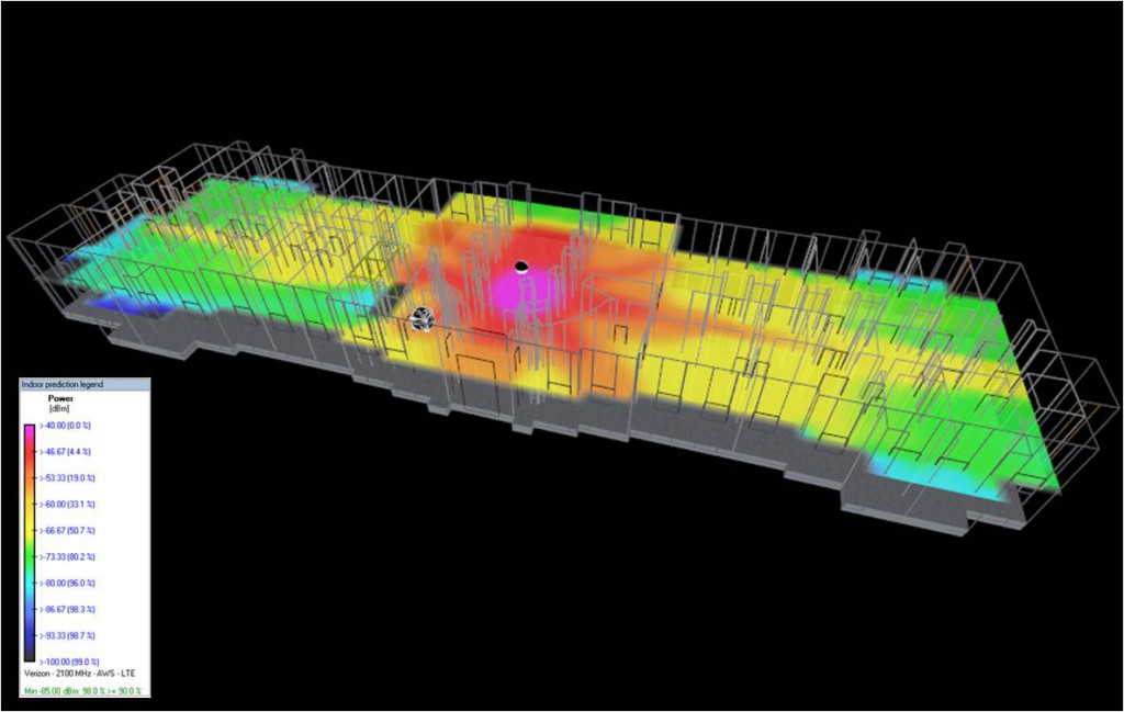
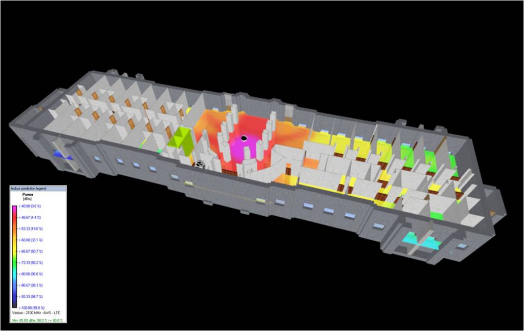
I-DAS receive signal strength for 2100 MHz LTE taking into account all wall, door, and floor RF properties.
I-DAS Coverage for 2100 MHz LTE Design
Indoor RF Coverage
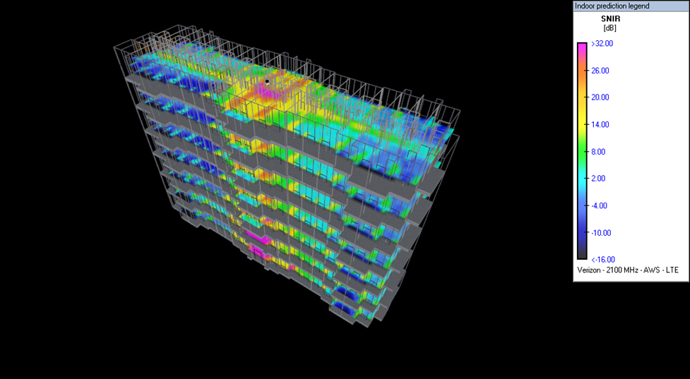
I-DAS signal-to-noise heat map for a given in-building design assuming 2100 MHz LTE.
I-DAS Nature of Path for 2100 MHz LTE
Indoor RF Coverage
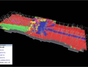
Nature of path for 2100 MHz LTE on first floor of Hotel for given design.
I-DAS Electric Field Strength
Indoor RF Coverage
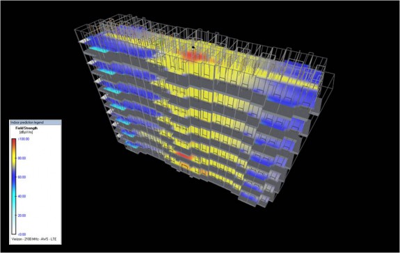
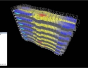
Calculated E-Field for I-DAS design to ensure compliance with maximum permissible exposure (MPE) levels.
I-DAS Receive Signal Strength
Indoor RF Coverage
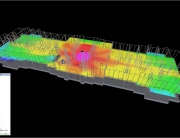
RSL for 2100 MHz LTE on first floor of Hotel for given design (transparent walls).
I-DAS Receive Signal Strength
Indoor RF Coverage
RSL for 2100 MHz LTE on first floor of Hotel for given design (non-transparent walls).
LTE RSRQ RSL for 2100 MHz LTE
Indoor RF Coverage
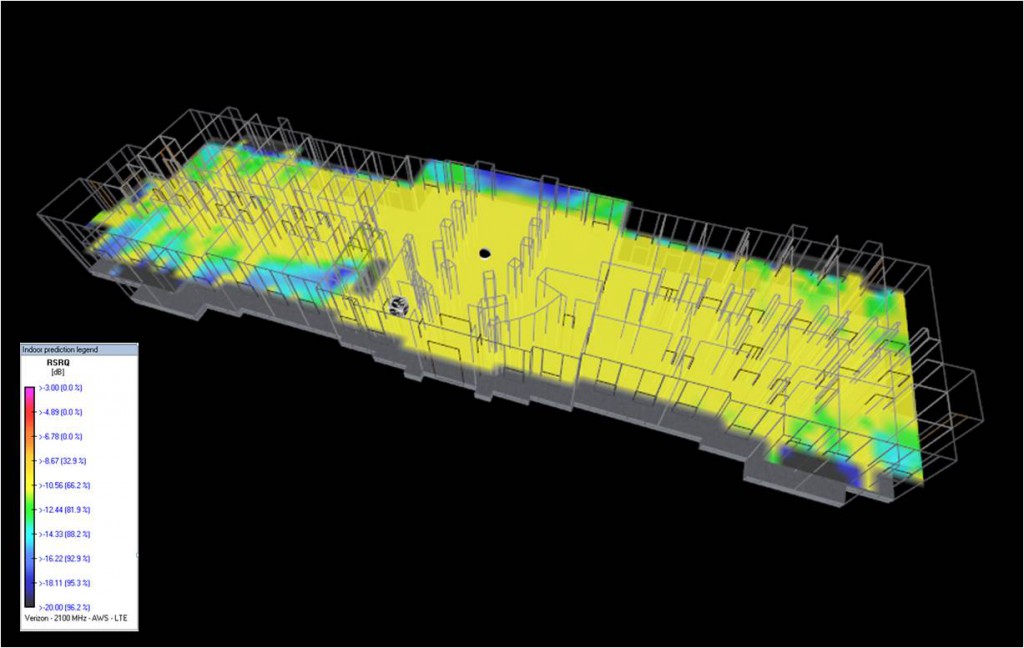
LTE RSRQ for 2100 MHz LTE on first floor of Hotel for given design.
Building CAD Drawings for I-DAS Analysis
Indoor RF Coverage
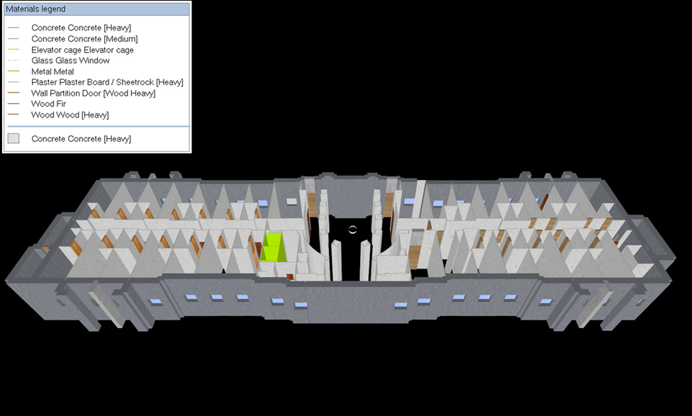
Hotel CAD drawing created from scratch using jpg image files of floor plans. The shown building materials are associated with known RF properties for the indoor coverage analysis.
Building CAD Imported into Google Earth
Indoor RF Coverage
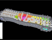
Ballantyne Hotel CAD design performed in iBwave and imported into Google Earth (Inset is view of building in iBwave before import).
LTE AWS RSRP 3D Heat Map
Indoor RF Coverage
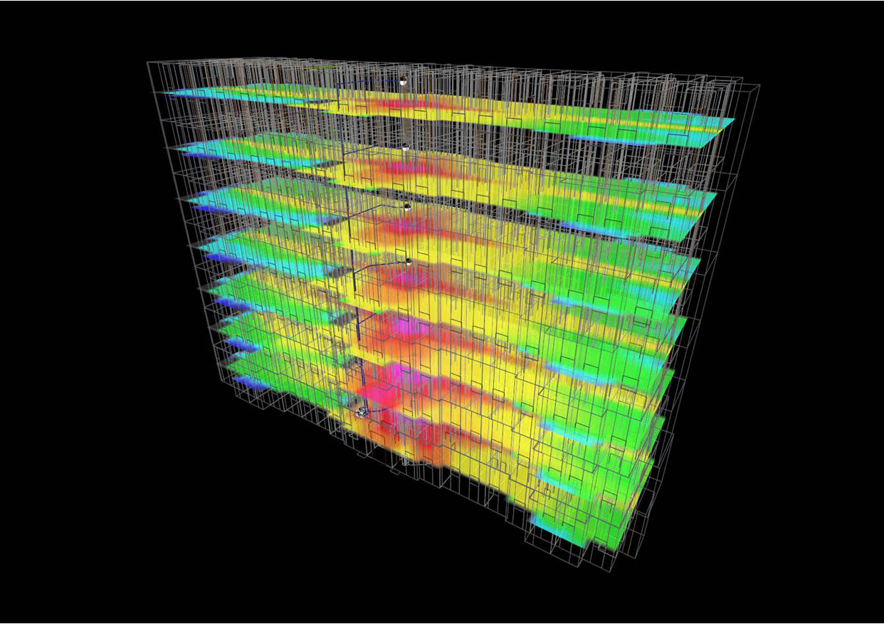
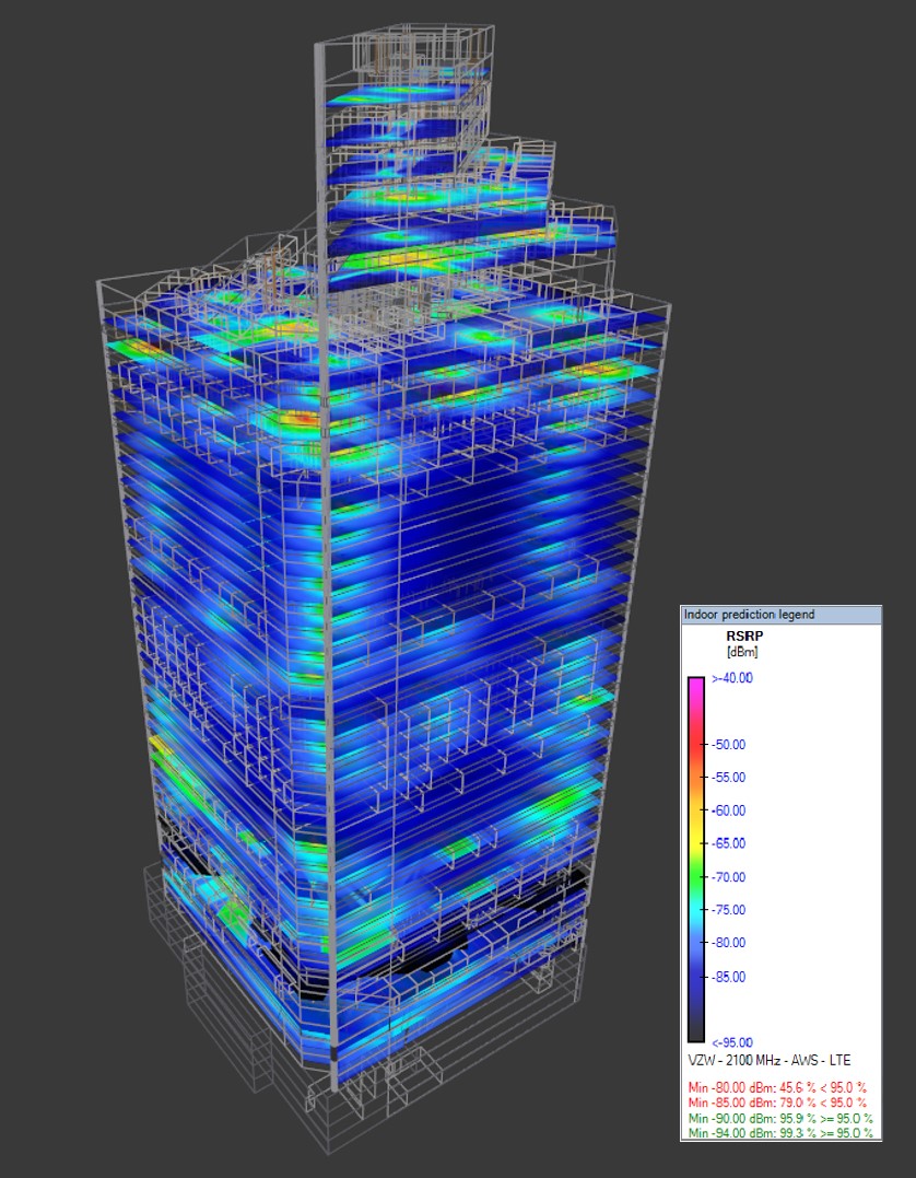
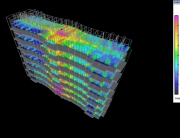
LTE AWS RSRP I-DAS Heat Map for a 42 story building (iBwave design). All CAD and RF design work done by SpectraNet.
I-DAS CAD Design for a 42 Story Building
Indoor RF Coverage
CAD design of a 42 story building in Minneapolis. Building and floor plan CAD drawings were created manually based on image drawings, and measurements performed on-site.

